Build vPC port-channels with automatic configuration mirroring—ensuring consistency across both vPC peers.
Much like the access interface you modified, this section focuses on creating a brand new Logical Interface—a vPC interface from your Site1-L1 and Site1-L2 vPC pairs.
ND's config mirroring feature automatically replicates port-channel settings to both vPC peers, preventing common misconfiguration issues.
Since these switches reside inside of a CML environment, the vPC interface will not actually come up. But this showcases the simplicity of ND when configuring vPC. These steps can be repeated or further automated for any number of vPC interfaces.
Clear the filter used in the previous section by:
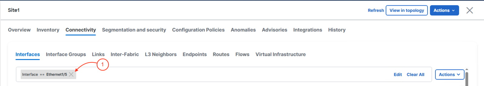
With the filter cleared in preparation for applying another one later, it's time for you to create an interface:
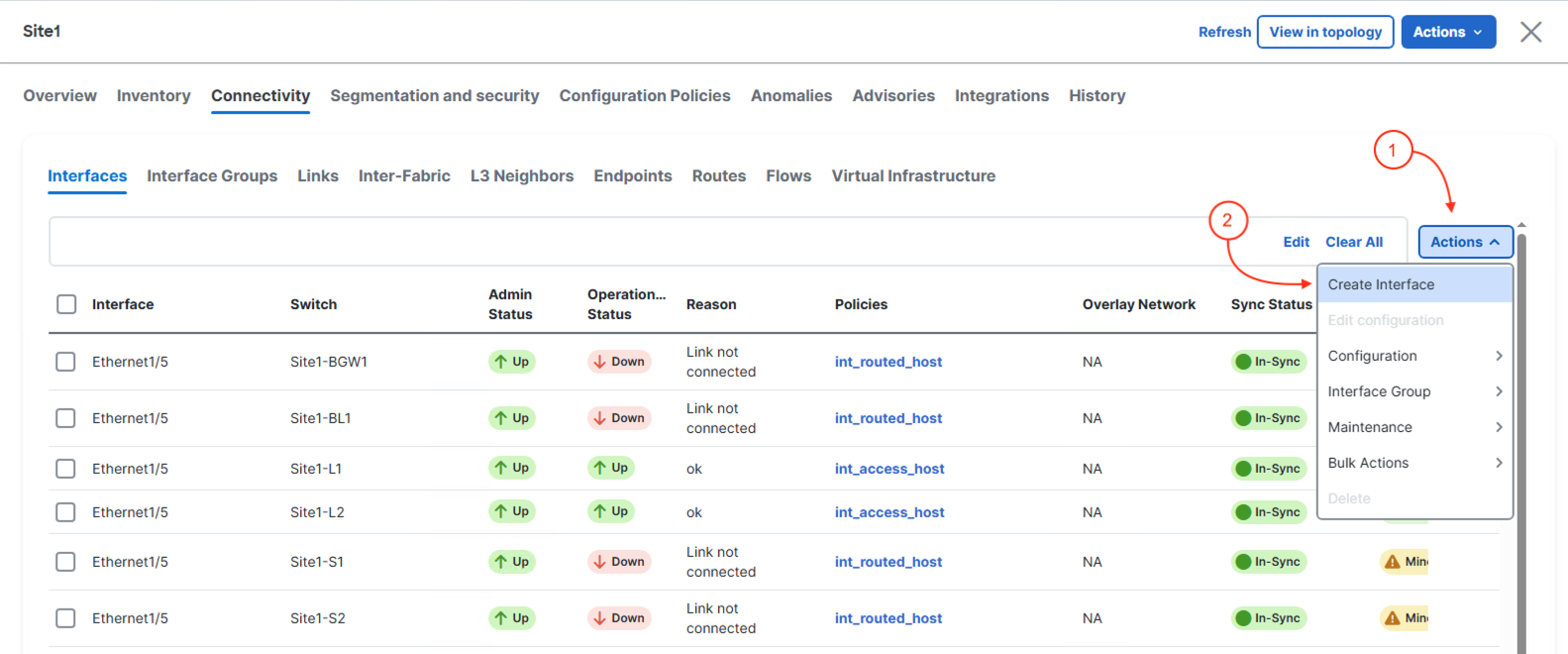
The Create Interface wizard supports creating many different types of interfaces and is dynamic in what is displayed to you based on the interface type selected.
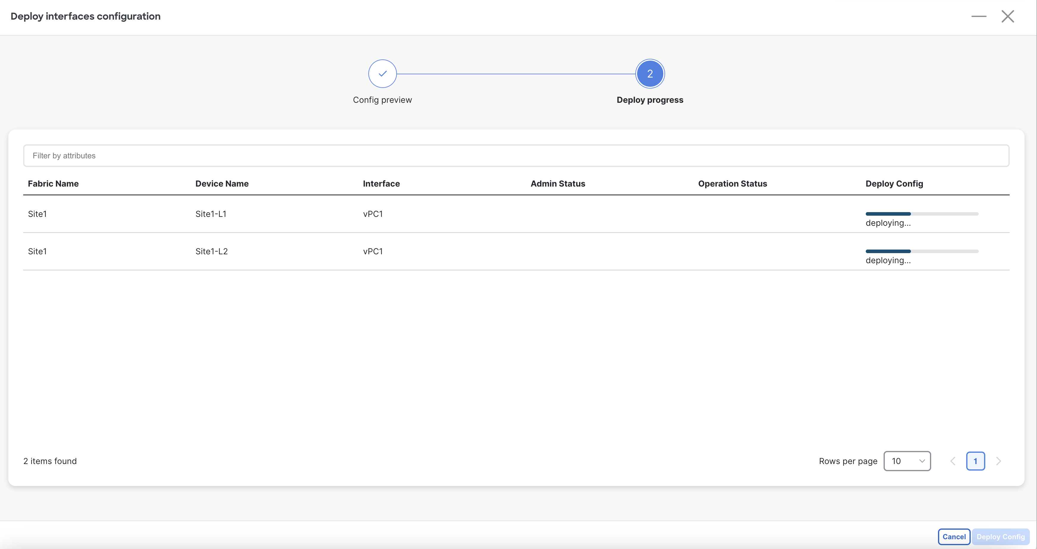
After clicking Deploy, Nexus Dashboard launches the Deploy interfaces configuration wizard. Review the pending configuration as desired. Once done:
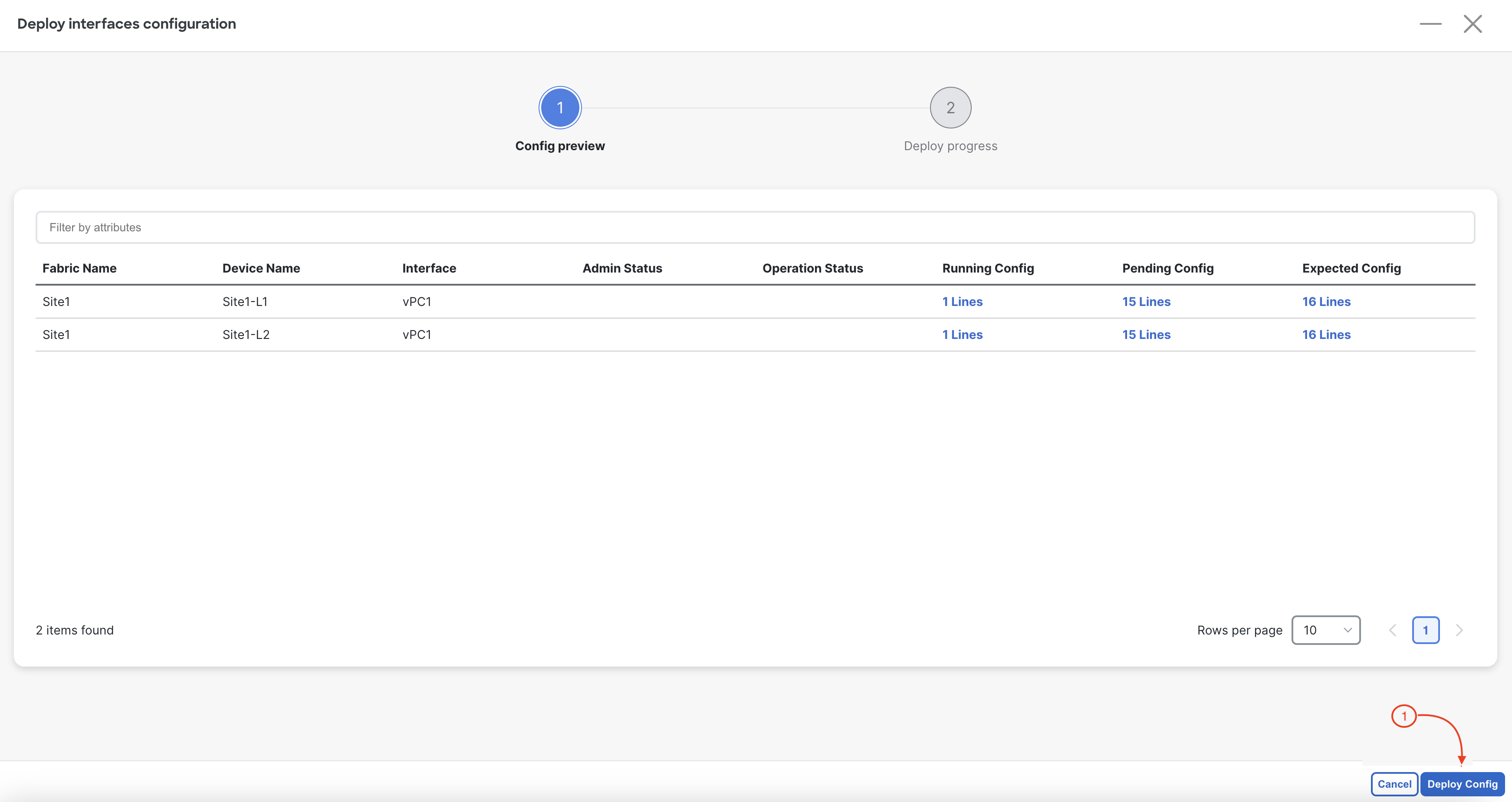
You will see the intended vPC interface configuration start being deployed for Port-Channel 1 (that is a vPC) with the Ethernet1/6 interface on Site1-L1 and Site2-L1 as members.